"*" indicates required fields
Why Choose C Mount Industrial Lenses for Machine Vision?
Machine vision is moving from isolated inspection stations into connected factories. MarketsandMarkets estimates that the global machine vision market will grow from about USD 13.7 billion in 2024 to USD 20.6 billion by 2029. This expansion increases pressure on every imaging component, including the lens. As machine-vision educator David Dechow explains, “Machine vision is the automatic extraction of information from images.” A reliable image begins before software analyzes a single pixel.
C Mount Industrial Lenses remain popular because they offer practical compatibility and flexible system design. Their standardized 1-inch, 32-thread mount fits many industrial cameras, filters, and extension accessories. Engineers can replace a lens without rebuilding the entire inspection station. That matters on a production line where downtime quickly becomes expensive. A 16 mm lens may capture a wider field, while a 50 mm lens can support closer inspection from a controlled distance. Aperture, distortion, sensor coverage, and working distance still require careful testing.
The choice is rarely perfect. A low-cost lens may produce soft corners or visible distortion. A high-resolution camera cannot recover detail that the optics never captured. According to the Association for Advancing Automation, vision systems support inspection, measurement, identification, and robotic guidance across modern manufacturing. C Mount Industrial Lenses can serve these tasks, but only when matched to the sensor and lighting. Real-world trials matter. A printed target, metal edge, or barcode under actual factory lighting often reveals weaknesses that specifications hide. Good engineering begins with evidence, not assumptions.
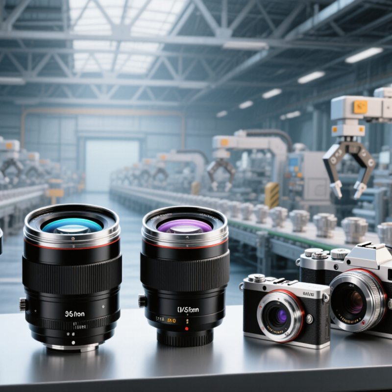
C-mount industrial lenses are optical components designed to connect with machine vision cameras through a standardized 1-inch, 32-thread mount. Their role is more than simply enlarging an image. They collect light, control perspective, and project a measurable image onto the camera sensor. The standard flange focal distance is 17.526 millimeters, which supports consistent lens and camera integration. This makes C-mount systems practical for automated inspection, measurement, and positioning tasks.
In a production line, lens selection directly affects inspection reliability. A lens with the wrong focal length may miss the edges of a metal part or create an unsuitable working distance. For example, a 16-millimeter lens can capture a wider area, while a 50-millimeter lens usually offers a narrower view with less perspective distortion. Operators should check sensor size, image circle, resolution, aperture, and distortion before installation. A printed calibration grid can reveal errors that are difficult to notice on a normal product image. Lighting matters too. Even an excellent lens may produce weak results under uneven illumination.
Sharpness at the center is not enough. Corners can lose detail, especially with large sensors or open apertures. I have seen inspection setups pass basic tests but fail when parts moved slightly outside the optical axis. That is a useful warning. Real testing should include edge samples, different working distances, and repeated measurements. Some specifications also depend on manufacturing tolerance and focus adjustment. The lens should be evaluated as part of the complete vision system, not as an isolated component.
Why Choose C Mount Industrial Lenses for Machine Vision?
C-mount lenses remain popular because their mechanical standard is clear and widely supported. The mount uses a 1-inch, 32-thread interface. Its flange focal distance is 17.526 mm. This makes camera replacement and lens adjustment relatively predictable. However, compatibility is not automatic. The lens must cover the sensor’s image circle. A lens designed for a 2/3-inch sensor may create dark corners on a 1.1-inch sensor. Check focal length, pixel size, working distance, and distortion together. According to the International Federation of Robotics’ World Robotics 2024 report, 541,302 industrial robots were installed globally in 2023. More automated inspection increases the need for stable, interchangeable optical systems.
Optical performance also requires measurable evidence. EMVA 1288 defines methods for evaluating quantum efficiency, signal-to-noise ratio, dynamic range, and spatial non-uniformity. These metrics are more useful than sharpness claims alone. A short focal length can capture a wide field, but it may increase perspective distortion. A longer focal length improves framing from a fixed distance, yet it needs more space. C-mount is flexible, but not flawless.
Tips: Confirm the camera’s sensor format before ordering. Measure the working distance on the real production line. Leave some image-circle margin. Test reflective parts under actual lighting. A lens that looks sharp on a test chart can still fail beside metal edges, vibration, or uneven illumination. Recheck focus after thermal changes. Small alignment errors matter.
Key optical features and compatibility standards
1-inch, 32-thread-per-inch (1"-32 UN) mounting thread with a 17.526 mm flange focal distance.
CS-mount cameras use a 12.5 mm flange focal distance. A 5 mm spacer can generally adapt a C-mount lens to a CS camera.
The lens image circle should be at least as large as the sensor diagonal to avoid corner vignetting.
The chart shows approximate active sensor diagonals calculated from representative sensor dimensions for common machine-vision formats. Actual dimensions vary by sensor design.
Why Choose C Mount Industrial Lenses for Machine Vision?
C-mount lenses support machine vision applications through practical mechanical and optical flexibility. Their 1-inch, 32-thread interface fits many industrial cameras, while the 17.526 mm flange distance simplifies system alignment. A 2024 MarketsandMarkets report valued the global machine vision market at about USD 13.7 billion in 2023. It projects growth to USD 20.7 billion by 2028. This expansion increases demand for dependable lens-camera matching.
In a packaging line, a C-mount lens can capture labels, seals, and surface defects under fixed lighting. Operators can change focal lengths without replacing the entire imaging system. That matters when a conveyor width changes from 200 to 600 millimeters. Lens selection still requires care. Sensor size, working distance, distortion, and aperture must agree. A wide lens may cover more area, but it can bend straight edges near the frame. That mistake is easy to miss.
C-mount designs also support filters, extension rings, and protective housings. These details help in dusty inspection areas. According to the International Federation of Robotics, global factory robot installations reached 541,302 units in 2023. More automated cells mean more cameras operating beside moving equipment. In my experience, vibration and glare often cause more failures than resolution. A rigid mount and controlled lighting remain essential. C-mount is useful, not magical.
| Selection Dimension | Typical C-Mount Lens Characteristics | Machine Vision Benefit | Common Application Examples |
|---|---|---|---|
| Mount Interface | 1-inch-32 UN 2A/2B threaded mount, commonly identified as C-mount. | Provides a widely used mechanical interface for industrial cameras, adapters, and imaging accessories. | Inspection stations, production-line cameras, laboratory imaging, and embedded vision systems. |
| Focal Length Options | Common fixed focal lengths include approximately 6 mm, 8 mm, 12 mm, 16 mm, 25 mm, 35 mm, 50 mm, and 75 mm. | Allows the field of view and working distance to be matched to the inspection area. | Wide-area conveyor monitoring, component inspection, code reading, and detailed measurement. |
| Sensor Compatibility | Compatibility depends on the lens image circle; typical industrial configurations support formats such as 1/3-inch, 1/2-inch, 2/3-inch, 1-inch, and larger formats. | Correct image-circle selection helps prevent corner shading and preserves usable pixels across the sensor. | Monochrome or color cameras using area sensors for 2D inspection and guidance. |
| Field of View | Shorter focal lengths generally provide a wider field of view; longer focal lengths provide a narrower field of view at the same distance. | Supports application-specific framing without changing the camera position. | Tray inspection, packaging verification, surface inspection, and part presence checks. |
| Working Distance | Many industrial C-mount lenses offer adjustable focus, while the usable working-distance range varies by focal length and lens design. | Helps maintain focus when cameras must be mounted outside a guarded or moving area. | Robotic cells, enclosed machinery, safety-guarded lines, and close-range inspection fixtures. |
| Iris Control | Manual iris adjustment is common; some industrial designs provide locking iris and focus rings for fixed installations. | Enables control of light transmission and depth of field, reducing focus variation caused by changing part heights. | Dimensional checks, multi-height assemblies, and applications with controlled LED lighting. |
| Depth of Field | Depth of field is influenced by aperture, focal length, object distance, sensor size, and the required image detail. | Appropriate aperture selection can keep uneven or three-dimensional parts within acceptable focus. | Connector inspection, molded-part inspection, fastener verification, and component orientation checks. |
| Optical Resolution | Resolution varies by lens model and image height; the lens should be selected to resolve the smallest feature required by the camera system. | Prevents the lens from becoming the limiting factor in image quality and measurement repeatability. | Scratch detection, edge inspection, print verification, and fine-feature recognition. |
| Distortion | Distortion differs by focal length and optical design; wide-angle lenses generally require closer attention to geometric distortion. | Lower distortion improves dimensional accuracy and simplifies calibration for measurement tasks. | Position measurement, dimensional gauging, alignment, and grid-based calibration. |
| Lighting Compatibility | Lens performance depends on aperture, transmission, surface coatings, and the wavelength range used by the lighting system. | Works with common visible-spectrum machine-vision lighting when spectral and exposure requirements are matched. | Backlighting, coaxial lighting, ring lighting, dome lighting, and line lighting setups. |
| Mechanical Stability | Lockable focus and iris adjustments are available on many industrial designs; rigid mounting is still required. | Reduces the risk of focus or exposure changes caused by vibration and repeated machine operation. | High-speed production lines, pick-and-place equipment, presses, and automated inspection cells. |
| System Integration | Compatible with standard C-mount camera bodies, extension rings, protective windows, and selected filters. | Simplifies replacement, prototyping, and integration with existing machine-vision hardware. | New system design, camera upgrades, spare-part planning, and multi-camera installations. |
| Selection Priority | Choose based on sensor size, required field of view, working distance, smallest feature, lighting, distortion tolerance, and environmental conditions. | Creates a balanced optical system instead of selecting a lens solely by focal length or price. | Reliable inspection systems requiring repeatable images and stable production performance. |
Why Choose C Mount Industrial Lenses for Machine Vision?
Factors for Selecting the Right C-Mount Industrial Lens
Selecting a C-mount industrial lens starts with the camera sensor, not the lens catalog. The lens must cover the sensor without dark corners or unwanted image loss. Match the lens image circle with the sensor format carefully. A mismatch can remain hidden during bench testing. Measure twice.
Focal length determines the field of view and working distance. A shorter focal length sees more area, while a longer one provides tighter inspection details. Check the required object size, camera position, and available space before choosing. Aperture also matters. More light can reduce exposure time, but wide apertures may reduce depth of field. Light changes everything. In practical trials, reflective metal often needs controlled illumination rather than a brighter lens.
Resolution should match the smallest defect being inspected. Review optical test data, distortion values, and edge sharpness across the full image. Mechanical stability deserves equal attention. Locking rings, solid mounts, and repeatable focus help maintain reliable measurements after vibration or temperature changes. If the application uses filters, enclosures, or coaxial lighting, confirm thread and clearance requirements early. I have seen teams choose a sharp lens that later failed because its working distance was inconvenient. That mistake is easy to make. Test the complete camera, lens, lighting, and target together before production approval. A perfect specification sheet cannot replace a realistic trial.
Installation, Calibration, and Maintenance Considerations
Choosing a C-mount industrial lens requires more than checking focal length. Installation begins with a clean mounting surface and a correctly matched sensor format. Tighten the lens evenly, but do not force the thread. Excess pressure can shift optical alignment. Set the working distance before locking focus. A small spacer may help when the lens cannot reach the required position.
Calibration should use a fixed test target under production lighting. Check focus across the entire image, not only at the center. Edge softness may indicate poor alignment, incorrect flange distance, or lens distortion. Adjust aperture carefully. A narrow aperture increases depth of field, but it can reduce available light. I have seen operators improve focus while accidentally creating noisy images. That trade-off deserves review.
Maintenance is usually simple, but consistency matters. Remove dust with clean air before using a lens-safe cloth. Never wipe dry particles across the glass. Inspect the mount after vibration, temperature changes, or machine relocation. Record focus, aperture, and working distance settings. This record saves time during replacement. Still, records can become outdated. Recheck calibration after major lighting or software changes. A lens may remain physically secure while image quality slowly declines. That subtle drift is easy to miss.
"*" indicates required fields